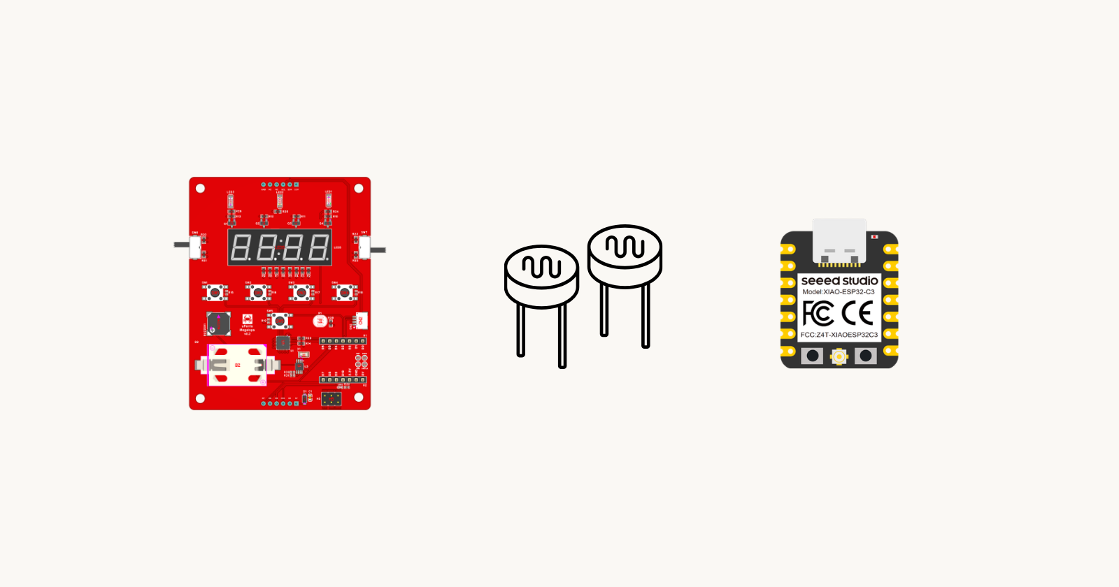
Embedded Rust BSP with µFerris & XIAO: Getting started with µferris-bsp

This is the second post in the µFerris & Xiao BSP series. If you haven't yet, start with Getting Started with µFerris & Xiao where we assembled the board, set up the toolchain, and blinked an LED. This post picks up from there.
Introduction
In the last post, we blinked µFerris's onboard LED by reaching straight into esp-hal. Grabbing a GPIO pin and toggling it in a loop. That works, but it ties your code to one specific pin on one specific chip. Move the LED on a future board revision or move the controller to a different board, and every example breaks.
This is exactly the problem a Board Support Package (BSP) solves. Instead of talking to pins, you talk to the board: led1_on(), read_ldr(), buzz_on(). The BSP knows which pin, which peripheral, and which HAL call each maps to, and it handles the peripheral configuration for you.
In this post we'll dig into the uferris-bsp crate and write one small program against it: read the light-dependent resistor (LDR) and show its raw value on the board's 4-digit seven-segment display. We talk to the board, not the pins. By the end, you'll have a project wired to the BSP and a working example running on real hardware.
📚 Knowledge Prerequisites
To follow along, you'll need to know:
Basic knowledge of coding in Rust.
Familiarity with no-std development in Rust.
💾 Software Setup
In this post, we are going to demonstrate usage of some examples using the uferris-bsp. You can set up the basic template for the project with one command using xiao-generate. Make sure you set up the project for the ESP32-C3 with the uferris-bsp option activated. You do not need to add any other BSP options. You can find more information here.
🛠 Hardware Setup
Required hardware includes:
USB-C cable for flashing and power
µFerris Megalops baseboard

- A Seeed Studio Xiao ESP32-C3 mounted on the carrier

🔌 Connections
Since we are using pre-built hardware (µFerris), we don't need to make any connections.
👨🎨 Software Design
What the BSP Gives You
Simply put, a Board Support Package (BSP) is a crate. By importing it, you get board abstractions rather than microcontroller abstractions from a HAL crate. BSPs actually build on top of HALs and are more or less HAL drivers. I'll cover this in more detail in the next post.
The uferris-bsp
uferris-bsp is a BSP for the µFerris carrier board. Instead of handing you raw GPIOs and peripherals, it gives you a single board handle with named methods referencing components on the board such as:
led1_on()/led1_off()to control one of the onboard user LEDs.read_ldr()to read the ambient-light sensor, as a raw ADC reading.buzz_on()/buzz_off()to control the piezo buzzer.
…plus other methods for other board functions.
You call these instead of configuring a GPIO output pin, an analog pin, or an I2C bus yourself. The crate does that setup once, inside an initialization method,uferris_init, and hands back a ready-to-use board.
We're targeting the XIAO ESP32-C3 in this post. However, which board the crate wires up is chosen at compile time via a feature flag which we'll set in Cargo.toml below. In essence, you can use any supported controller simply by adjusting the feature flag.
Light Intensity Reading Example
In this post, we'll demonstrate how to use the BSP to read light intensity. We will read the raw light-intensity value from the light-dependent resistor (LDR) circuit every second and display it on the board's 4-digit seven-segment display. This works because the LDR reading is a 12-bit value, so the highest value to show needs no more than 4 digits (2^12 = 4096). As such, the steps are as follows:
Initialize the BSP.
Read the LDR.
Show the Reading on the seven-segment display.
Hold the value for 1 second.
Go back to step 2
Show the Reading on the Seven-Segment Display
This is relative to step 3 in the design, from the uferris-bsp docs; notice the abstraction that allows us to write to the seven-segment display:
pub fn write_seven_segment_digit(
    &mut self,
    digit: SevenSegDigit,
    value: Option<u8>,
) -> Result<(), I2C::Error>
It allows us to define the digit position and its value. value can be None if we want to leave the digit blank (Ex., leading zeros). This means that we can activate one at a time. This is because the seven-segment activation lines are shared. This is not unusual because the alternative would require many pins. This might seem problematic because it means I can activate only one digit while the others are off. However, if we cycle between the digits fast enough, the human eye cannot sense the change. This is essentially what all displays do. The minimum frequency is typically around 30 Hz, but it is better to go higher. Anything less manifests as flicker. Meaning that the human eye can detect that the LED is being refreshed.
This means we need a light-display refresh algorithm. The steps are as follows:
Split the LDR Reading Into Digits: The seven-segment display shows one digit per position, so we need to break the reading into its thousands, hundreds, tens, and units.
Multiplex Digits: For each digit, activate the LED and hold its value for 1 ms.
Repeat step 2 250 times.
So relative to the numbers. 1 ms means that for 4 digits, I spend 4 ms per pass. This equates to a 250 Hz (1/4ms) refresh rate, which is well above the minimum of 30Hz required to avoid flicker. Now, relative to the 250 times repeat. This depends on how long I want to hold the same value on the display. So one pass is 4ms, and I want a 1-second hold time (as defined in the earlier step); this means I need to show the same value 250 times (4ms/pass * 250 passes = 1,000 ms).
👨💻 Code Implementation
📥 Crate Imports
The following imports are required:
use esp_backtrace as _;
use esp_hal::clock::CpuClock;
use esp_hal::delay::Delay;
use uferris_bsp::{uferris_init, SevenSegDigit};
esp_backtraceis needed to register the panic handler and exception backtrace. We never call it directly, hence theas _.esp_hal::clock::CpuClockandesp_hal::delay::Delayare the only twoesp-halitems we'll need: one to configure the clock during setup, the other to get a blocking delay.uferris_bsp::{uferris_init, SevenSegDigit}is the BSP itself: theuferris_initfunction that hands us the board, andSevenSegDigitis a convenience enum we use to address each of the four display digits.
🎛 Configure Device and BSP
Instantiation Code
Before the application code, we need to instantiate the BSP and get a handle so we can call its methods. Here are the steps:
1️⃣ Obtain a Handle for the Device Peripherals: To initialize the BSP, we would require a handle to the device peripheral abstractions. This allows the BSP to build its own abstractions on top of the peripheral abstractions. As such, in embedded Rust, as part of the singleton design pattern, we have to take the PAC-level device peripherals. This is typically done using the take() method.
esp-hal is a bit different; instead of using take() it has an init() method. init essentially does the same thing as take where it provides a handle to the device peripherals. Additionally, it allows you to configure the HAL instance by passing the configuration as a parameter. This configuration is captured at the HAL crate level in the esp_hal::Config struct and lets you configure device-level parameters like clock speed.
Here I create a device peripheral handler named peripherals as follows:
let config = esp_hal::Config::default().with_cpu_clock(CpuClock::max());
let peripherals = esp_hal::init(config);
3️⃣ Instantiate BSP & obtain handle: The BSP is instantiated simply by calling the uferis_init method and passing the peripherals handle. Afterward, we get a handle to access all the uferris_bsp methods as follows:
let mut uferris = uferris_init(peripherals);
That's it for configuration; now we can move on to the application code.
⚠️ Note that the first step is
esp-halspecific and are the only hal (or controller) specific ones in the code. We will not be using any HAL abstractions in the code, we only need these instances to pass its to the BSP so it can use it. Different controllers might have different abstractions or approaches for obtiaining peripherals.
📱 Application Code
With the handle in place, the application is a single loop. Here are the steps:
1️⃣ Create a Delay Handle: We need a blocking delay to pace the digit refresh. esp-hal provides one through Delay, and the delay_ms method comes from the DelayNs trait we imported earlier.
let mut delay = Delay::new();
2️⃣ Read the LDR: Each pass around the loop, we grab a fresh raw reading from the ambient-light sensor. read_ldr() returns a u16 for a 12-bit reading (0–4096).
let reading = uferris.read_ldr();
3️⃣ Split the Reading Into Digits: The seven-segment display shows one digit per position, so we break the reading into its thousands, hundreds, tens, and units. Integer division and modulo do the work:
let digits = [
    (reading / 1000 % 10) as u8,
    (reading / 100 % 10) as u8,
    (reading / 10 % 10) as u8,
    (reading % 10) as u8,
];
4️⃣ Multiplex the Digits: write_seven_segment_digit activates a single digit's common line and blanks the others. Each write_seven_segment_digit call takes the digit selector (SevenSegDigit::Digit1..Digit4) and the value to show, wrapped in Some (None blanks the digit). It returns a Result because it talks to the I/O expander over I2C, so thats why we unwrap() it.
We hold each digit for 1 ms, then repeat the whole four-digit sweep 250 times. That's roughly one second of steady display per reading, which stands in for the "wait 1 second" step; the display is never actually idle; it's being refreshed the entire time.
for _ in 0..250 {
    uferris.write_seven_segment_digit(SevenSegDigit::Digit1, Some(digits[0])).unwrap();
    delay.delay_ms(1);
    uferris.write_seven_segment_digit(SevenSegDigit::Digit2, Some(digits[1])).unwrap();
    delay.delay_ms(1);
    uferris.write_seven_segment_digit(SevenSegDigit::Digit3, Some(digits[2])).unwrap();
    delay.delay_ms(1);
    uferris.write_seven_segment_digit(SevenSegDigit::Digit4, Some(digits[3])).unwrap();
    delay.delay_ms(1);
}
5️⃣ Loop: After the refresh window elapses, execution returns to step 2, reads the LDR again, and the display updates with the new value.
❓ What's Next
You've now used the BSP as a black box. We called led1_on() and write_seven_segment_digit() without seeing how either is wired up. In the next post, we start building a BSP from scratch: discuss what a BSP actually is, and how to write the uferris_init function and board struct for a single controller, the Xiao ESP32-C3. That boilerplate becomes the base the rest of the series extends, one peripheral at a time: LED, buzzer, LDR, I2C, RTC, and the I/O expander.
📱 Full Application Code
Here's the complete program, ready to drop into src/main.rs:
#![no_std]
#![no_main]

use esp_backtrace as _;
use esp_hal::clock::CpuClock;
use esp_hal::delay::Delay;
use embedded_hal::delay::DelayNs;
use uferris_bsp::{uferris_init, SevenSegDigit};

#[esp_hal::main]
fn main() -> ! {

    // Initalize the HAL & get peripherals handle
    let config = esp_hal::Config::default().with_cpu_clock(CpuClock::max());
    let peripherals = esp_hal::init(config);

    // Initialize the BSP and get a handle
    let mut uferris = uferris_init(peripherals);

    // Blocking delay used to pace the display refresh
    let mut delay = Delay::new();

    loop {
        // Read the raw LDR value (0..=4096)
        let reading = uferris.read_ldr();

        // Split it into four decimal digits
        let digits = [
            (reading / 1000 % 10) as u8,
            (reading / 100 % 10) as u8,
            (reading / 10 % 10) as u8,
            (reading % 10) as u8,
        ];

        // Multiplex the four digits
        // & Hold for 1 second
        for _ in 0..250 {
            uferris.write_seven_segment_digit(SevenSegDigit::Digit1, Some(digits[0])).unwrap();
            delay.delay_ms(1);
            uferris.write_seven_segment_digit(SevenSegDigit::Digit2, Some(digits[1])).unwrap();
            delay.delay_ms(1);
            uferris.write_seven_segment_digit(SevenSegDigit::Digit3, Some(digits[2])).unwrap();
            delay.delay_ms(1);
            uferris.write_seven_segment_digit(SevenSegDigit::Digit4, Some(digits[3])).unwrap();
            delay.delay_ms(1);
        }
    }
}
Conclusion
A BSP trades a handful of raw HAL calls for a stable, board-shaped API. Instead of grabbing a GPIO and an ADC channel by hand, we called uferris_init() once and then read the ambient-light sensor with a single read_ldr() and drove the display withwrite_seven_segment_digit(), no pin numbers in sight. This is an abstraction layer that adds overesp-hal. It is often easier to think about the board than about pin numbers; that's exactly the trade you want.