Embedded Rust BSPs with uFerris & Xiao: I2C Support
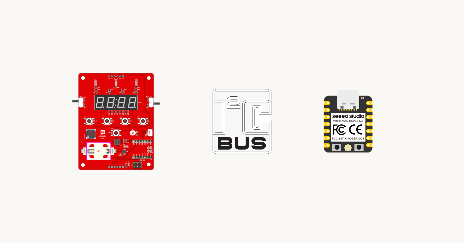
This is the seventh post in the µFerris & Xiao BSP series, where we build a Board Support Package from scratch, one peripheral at a time. In the previous post, we added the LDR using the ADC. This post adds the I2C bus, which is the first peripheral that talks to other chips rather than driving a single component.
Series Past Posts
Introduction
In the last post, we added the LDR using the ADC, which was the last component wired directly to a chip pin. Everything we have added so far is a single part on the board: one LED, one switch, one buzzer, one LDR. Each has a pin, and the BSP owns that pin.
This post adds the I2C bus. The µFerris routes the XIAO's I2C pins to an I/O Expander, an RTC, and a Qwiic connector, so you can plug in any Qwiic sensor or display without wiring. The bus differs from the earlier components in one way: it is not a component. It is a path to components, and the BSP does not always know ahead of time what will be sitting at the other end. That changes what the control functions look like. Rather than a function per part on the board, we get a small set of functions that move bytes to and from an address.
For this post, we set aside who owns the bus. The board struct holds the driver, and every transaction goes through it. The next post adds the first I2C device that lives on the µFerris itself, and that is where more than one part of the BSP needs the same bus.
Let's get started.
📚 Knowledge Prerequisites
To understand the content of this post, you need the following:
Basic knowledge of coding in Rust.
Basic understanding of embedded systems development concepts.
Familiarity with
no_stddevelopment in Rust, preferably usingesp-hal.Familiarity with I2C concepts.
Familiarity with the µFerris platform and flashing a XIAO module.
💾 Software Setup
All the code presented in this post is available in the µFerris & XIAO series repo. Every post in the series has its own self-contained Cargo project in a numbered folder. The code for this post lives in 07-i2c/:
git clone https://github.com/theembeddedrustacean/learn-bsp-rs
cd learn-bsp-rs/07-i2c
cargo run --release
The examples revolve around the ESP32-C3. If you want to follow along with a different device, please refer to the xiao-generate post for more detail.
🛠 Hardware Setup
The required hardware includes:
- µFerris Megalops Baseboard — the board this BSP is written for. Available from The Embedded Rustacean Store.

- Seeed Studio XIAO ESP32-C3 — the controller used throughout this phase of the series. Available from the SeeedStudio Store.

- USB-C cable for power, flashing, and serial output.
🔌 Connections
No connections are required. Every component the BSP will eventually drive is prewired; you only need to assemble the board. If you haven't assembled the board yet, this post walks through it.
The peripheral added in this post is connected on the µFerris as follows:
| Signal | XIAO Pin | Notes |
|---|---|---|
| SDA | GPIO6 | I2C data line, routed to the Qwiic connector. |
| SCL | GPIO7 | I2C clock line, routed to the Qwiic connector. |
👨🎨 Software Design
This post builds on the BSP from the previous post, where we added the LDR. This post assumes you understand that code. Recall the BSP code is composed of three parts; The Board struct, The Board Initialization Function, and The Board Control Functions. Each post adds to all three.
The Board Struct
The I2C driver in esp-hal is a single type, I2c, from esp_hal::i2c::master. It owns the peripheral and the two pins, and it runs transactions on request. One object covers the whole bus, so unlike the ADC there is nothing to pair up. The board struct gains a single member. This is the form of the updated struct:
/// A handle to the µFerris board and everything on it.
pub struct UFerris {
    led1: Output<'static>,
    sw_btn5: Input<'static>,
    buzzer: Channel<'static, LowSpeed>,
    ldr_driver: LdrAdc,
    i2c: I2c<'static, Blocking>,
}
Blocking marks the driver as the blocking rather than async flavor, as it did for the ADC. Notice that the member is named i2c and not after a component. The bus is not a component. It is infrastructure that components sit on, and this is the one member of the struct that does not correspond to a single part on the board.
The Board Initialization Function
We will update uferris_init to configure the bus. The steps are as follows:
Create an I2C
Configwith the bus frequency.Instantiate the I2C0 peripheral with that config.
Attach the SDA and SCL pins.
The Board Control Functions
We'll introduce three functions that the BSP will support:
| Function | Behaviour |
|---|---|
i2c_write(address, bytes) |
Sends bytes to the device at address. |
i2c_read(address, buffer) |
Reads from the device at address until buffer is full. |
i2c_write_read(address, bytes, buffer) |
Sends bytes, then reads into buffer without releasing the bus in between. |
Note that the functions take an address. This is the post's design decision. Earlier functions knew which component they were talking to because the component was fixed on the board. Part of what sits on the bus is not fixed; it depends on what is plugged into the Qwiic connector. So the address moves out of the BSP and into the caller's hands, and the BSP's job is only to move bytes. Note also that the functions return a Result, which none of the earlier ones did.
Optionally, you can add an i2c_bus() function that hands out a mutable reference to the driver, so that a driver crate written against embedded-hal can use the bus directly. That is left for the reader as an exercise.
Test Application Design
The test application scans the bus. The steps are as follows:
For every address from 0x08 to 0x77, send the address alone and check for an acknowledgment.
Print each address that acknowledges.
Print the number of devices found.
Wait 2 seconds (paces the scans).
Go back to step 1.
Addresses below 0x08 and above 0x77 are reserved by the I2C specification, so the scan skips them. You don't need to plug anything into the Qwiic connector. The µFerris has its own I2C devices, and the scan will find them.
👨💻 Code Implementation
1️⃣ Bring in the I2C types. Everything from the previous post stays. We add the driver, its configuration, and its error type:
use embedded_hal::pwm::SetDutyCycle;
use esp_hal::{
    Blocking,
    analog::adc::{Adc, AdcConfig, AdcPin, Attenuation},
    gpio::{DriveMode, Input, InputConfig, Level, Output, OutputConfig},
    i2c::master::{Config as I2cConfig, Error as I2cError, I2c},
    ledc::{
        LSGlobalClkSource, Ledc, LowSpeed,
        channel::{self, Channel, ChannelIFace},
        timer::{self, Timer, TimerIFace},
    },
    peripherals::{ADC1, GPIO2, Peripherals},
    time::Rate,
};
use static_cell::StaticCell;
Config and Error are renamed on import. esp_hal::Config already exists for the chip itself, and the LEDC code has configs of its own, so the I2C ones carry a prefix to keep them apart.
2️⃣ Define the bus frequency. Below is the code:
/// I2C bus clock, in kilohertz. Standard mode, which every I2C device supports.
const I2C_FREQ_KHZ: u32 = 100;
Note that 100 kHz is standard mode. Most devices also support 400 kHz fast mode, but the BSP does not know what will be plugged into the connector, so we pick a speed every device supports.
3️⃣ Populate the board struct. Add the driver as a single member to the board struct.
/// A handle to the µFerris board and everything on it.
pub struct UFerris {
    led1: Output<'static>,
    sw_btn5: Input<'static>,
    buzzer: Channel<'static, LowSpeed>,
    ldr_driver: LdrAdc,
    i2c: I2c<'static, Blocking>,
}
4️⃣ Populate the initialization function. In the init function, we now need to configure the bus, after the ADC setup from the previous post. Below is the code:
// Instantiate the I2C peripheral and attach its pins
let i2c = I2c::new(
    peripherals.I2C0,
    I2cConfig::default().with_frequency(Rate::from_khz(I2C_FREQ_KHZ)),
)
.expect("I2C configuration failed")
.with_sda(peripherals.GPIO6)
.with_scl(peripherals.GPIO7);

UFerris {
    led1,
    sw_btn5,
    buzzer,
    ldr_driver,
    i2c,
}
I2c::new returns a Result because the configuration can be rejected. The pins are attached afterward with with_sda and with_scl. These consume the driver and hand it back, which is why the whole thing is a single expression.
Note that the pins are routed, not fixed. The ESP32-C3 connects the I2C peripheral to whichever pins we name here through its GPIO matrix, which is why the driver needs to be told. That differs from the ADC, where the pin determines the converter.
5️⃣ Add the control functions. In the impl block on UFerris, we add three board methods that delegate to the driver:
// Write `bytes` to the device at `address`.
pub fn i2c_write(&mut self, address: u8, bytes: &[u8]) -> Result<(), I2cError> {
    self.i2c.write(address, bytes)
}

// Read from the device at `address` until `buffer` is full.
pub fn i2c_read(&mut self, address: u8, buffer: &mut [u8]) -> Result<(), I2cError> {
    self.i2c.read(address, buffer)
}

// Write `bytes` to the device at `address`, then read back into `buffer`
pub fn i2c_write_read(
    &mut self,
    address: u8,
    bytes: &[u8],
    buffer: &mut [u8],
) -> Result<(), I2cError> {
    self.i2c.write_read(address, bytes, buffer)
}
Each one is a thin wrapper around the driver method of the same name. write_read deserves a word. The write and the read happen under one transaction, with a repeated start between them and no stop until the read is done. This is the standard shape of a register read: the write selects a register, the read returns its contents, and the repeated start keeps the two together.
Note also that i2c_write accepts an empty slice. The driver then sends the address and nothing else, and reports whether anything acknowledged it. That is all a bus scan needs.
🏃♂️ Test Code & Run
#![no_std]
#![no_main]

use esp_backtrace as _;
use esp_hal::{clock::CpuClock, main};
use esp_println::println;
use uferris::{UFerris, uferris_init};

esp_bootloader_esp_idf::esp_app_desc!();

/// First and last addresses of the 7-bit range a device can sit at. The
/// addresses on either side are reserved by the I2C specification.
const FIRST_ADDR: u8 = 0x08;
const LAST_ADDR: u8 = 0x77;

#[main]
fn main() -> ! {
    // Configure the device and hand the peripherals to the BSP
    let config = esp_hal::Config::default().with_cpu_clock(CpuClock::max());
    let peripherals = esp_hal::init(config);
    let mut uferris: UFerris = uferris_init(peripherals);

    // Instantiate a delay provider
    let delay = esp_hal::delay::Delay::new();

    loop {
        println!("Scanning the I2C bus...");
        let mut found = 0;

        // Send each address on its own and see if anything acknowledges it
        for address in FIRST_ADDR..=LAST_ADDR {
            if uferris.i2c_write(address, &[]).is_ok() {
                println!("  device found at 0x{:02X}", address);
                found += 1;
            }
        }

        println!("Scan complete, {} device(s) found", found);

        // Scan every two seconds
        delay.delay_millis(2000);
    }
}
Flash it and open the monitor:
cargo run --release
The terminal prints a scan every two seconds. With nothing plugged into the Qwiic connector, two devices show up:
Scanning the I2C bus...
  device found at 0x22
  device found at 0x68
Scan complete, 2 device(s) found
Both are on the µFerris itself. 0x22 is the I/O expander, 0x68 is the real-time clock, and the following posts add each to the BSP. Plug a Qwiic device in while the application is running and its address appears on the next pass.
If the scan reports zero devices, the problem is on the bus rather than at any one address. Check that the XIAO is fully seated, since SDA and SCL are two of its pins.
✅ Conclusion
We added the I2C bus, and with it, the BSP can talk to devices not on the board. Getting there took one member in the struct and three functions that move bytes to and from an address the caller chooses.
The scan found two devices already on the board. The next post adds the first of them, the real-time clock, and with it the question this post set aside: what happens when more than one part of the BSP needs the same bus.
📱 Full Code
src/lib.rs
#![no_std]

use embedded_hal::pwm::SetDutyCycle;
use esp_hal::{
    Blocking,
    analog::adc::{Adc, AdcConfig, AdcPin, Attenuation},
    gpio::{DriveMode, Input, InputConfig, Level, Output, OutputConfig},
    i2c::master::{Config as I2cConfig, Error as I2cError, I2c},
    ledc::{
        LSGlobalClkSource, Ledc, LowSpeed,
        channel::{self, Channel, ChannelIFace},
        timer::{self, Timer, TimerIFace},
    },
    peripherals::{ADC1, GPIO2, Peripherals},
    time::Rate,
};
use static_cell::StaticCell;

/// The LEDC timer the buzzer channel reads its frequency from. The channel
static BUZZER_TIMER: StaticCell<Timer<'static, LowSpeed>> = StaticCell::new();

/// Resonant frequency of the µFerris buzzer, in hertz.
const BUZZER_FREQ_HZ: u32 = 2700;

/// I2C bus clock, in kilohertz. Standard mode, which every I2C device supports.
const I2C_FREQ_KHZ: u32 = 100;

/// The LDR and everything needed to read it.
///
/// A conversion needs both the ADC driver and the token for the pin being
/// sampled. They are paired here so the board struct keeps one member per
/// component.
pub struct LdrAdc {
    adc: Adc<'static, ADC1<'static>, Blocking>,
    pin: AdcPin<GPIO2<'static>, ADC1<'static>>,
}

impl LdrAdc {
    /// Run a conversion and return the raw count.
    pub fn read_raw(&mut self) -> u16 {
        nb::block!(self.adc.read_oneshot(&mut self.pin)).unwrap_or(0)
    }
}

/// A handle to the µFerris board and everything on it.
pub struct UFerris {
    led1: Output<'static>,
    sw_btn5: Input<'static>,
    buzzer: Channel<'static, LowSpeed>,
    ldr_driver: LdrAdc,
    i2c: I2c<'static, Blocking>,
}

/// Consume the raw chip peripherals and hand back a ready-to-use board.
pub fn uferris_init(peripherals: Peripherals) -> UFerris {

    // Instantiate LED 1
    let led1 = Output::new(peripherals.GPIO3, Level::Low, OutputConfig::default());

    // Instantiate SW5
    let sw_btn5 = Input::new(peripherals.GPIO5, InputConfig::default());

    // Instantiate the LEDC peripheral
    let mut ledc = Ledc::new(peripherals.LEDC);
    ledc.set_global_slow_clock(LSGlobalClkSource::APBClk);

    // Configure the timer attached to the LEDC
    let mut buzzer_timer = ledc.timer::<LowSpeed>(timer::Number::Timer0);
    buzzer_timer
        .configure(timer::config::Config {
            duty: timer::config::Duty::Duty14Bit,
            clock_source: timer::LSClockSource::APBClk,
            frequency: Rate::from_hz(BUZZER_FREQ_HZ),
        })
        .expect("buzzer timer configuration failed");

    // Promote the timer to 'static
    let buzzer_timer = BUZZER_TIMER.init(buzzer_timer);

    // Configure the LEDC Channel and attach pin.
    let mut buzzer = ledc.channel(channel::Number::Channel0, peripherals.GPIO4);
    buzzer
        .configure(channel::config::Config {
            timer: buzzer_timer,
            duty_pct: 0,
            drive_mode: DriveMode::PushPull,
        })
        .expect("buzzer channel configuration failed");

    // The LDR pin has to be enabled on the config before the ADC is built.
    let mut adc_config = AdcConfig::new();
    let ldr_pin = adc_config.enable_pin(peripherals.GPIO2, Attenuation::_11dB);
    let adc1 = Adc::new(peripherals.ADC1, adc_config);
    let ldr_driver = LdrAdc {
        adc: adc1,
        pin: ldr_pin,
    };

    // Instantiate the I2C peripheral and attach its pins
    let i2c = I2c::new(
        peripherals.I2C0,
        I2cConfig::default().with_frequency(Rate::from_khz(I2C_FREQ_KHZ)),
    )
    .expect("I2C configuration failed")
    .with_sda(peripherals.GPIO6)
    .with_scl(peripherals.GPIO7);

    UFerris {
        led1,
        sw_btn5,
        buzzer,
        ldr_driver,
        i2c,
    }
}

impl UFerris {
    /// Turn LED 1 on.
    pub fn led1_on(&mut self) {
        self.led1.set_high();
    }

    /// Turn LED 1 off.
    pub fn led1_off(&mut self) {
        self.led1.set_low();
    }

    /// Read switch 5.
    pub fn sw5_pressed(&mut self) -> bool {
        self.sw_btn5.is_low()
    }

    /// Sound the buzzer at the given duty, as a percentage from 0 to 100.
    pub fn buzz_on(&mut self, duty_percent: u8) {
        let _ = self.buzzer.set_duty_cycle_percent(duty_percent);
    }

    /// Silence the buzzer.
    pub fn buzz_off(&mut self) {
        let _ = self.buzzer.set_duty_cycle_fully_off();
    }

    /// Read the LDR as a raw ADC count.
    ///
    /// The value is a 12-bit conversion, so it ranges from 0 to 4095. It is
    /// not converted to lux or millivolts; see the crate docs for why.
    pub fn read_ldr(&mut self) -> u16 {
        self.ldr_driver.read_raw()
    }

    /// Write `bytes` to the device at `address`.
    ///
    /// An empty `bytes` sends the address alone, which is enough to find out
    /// whether a device is listening there.
    pub fn i2c_write(&mut self, address: u8, bytes: &[u8]) -> Result<(), I2cError> {
        self.i2c.write(address, bytes)
    }

    /// Read from the device at `address` until `buffer` is full.
    pub fn i2c_read(&mut self, address: u8, buffer: &mut [u8]) -> Result<(), I2cError> {
        self.i2c.read(address, buffer)
    }

    /// Write `bytes` to the device at `address`, then read back into `buffer`
    /// without releasing the bus in between.
    ///
    /// This is the shape of a register read: the write selects the register,
    /// the read returns its contents.
    pub fn i2c_write_read(
        &mut self,
        address: u8,
        bytes: &[u8],
        buffer: &mut [u8],
    ) -> Result<(), I2cError> {
        self.i2c.write_read(address, bytes, buffer)
    }
}
src/bin/main.rs
#![no_std]
#![no_main]

use esp_backtrace as _;
use esp_hal::{clock::CpuClock, main};
use esp_println::println;
use uferris::{UFerris, uferris_init};

esp_bootloader_esp_idf::esp_app_desc!();

/// First and last addresses of the 7-bit range a device can sit at. The
/// addresses on either side are reserved by the I2C specification.
const FIRST_ADDR: u8 = 0x08;
const LAST_ADDR: u8 = 0x77;

#[main]
fn main() -> ! {
    // Configure the device and hand the peripherals to the BSP
    let config = esp_hal::Config::default().with_cpu_clock(CpuClock::max());
    let peripherals = esp_hal::init(config);
    let mut uferris: UFerris = uferris_init(peripherals);

    // Instantiate a delay provider
    let delay = esp_hal::delay::Delay::new();

    loop {
        println!("Scanning the I2C bus...");
        let mut found = 0;

        // Send each address on its own and see if anything acknowledges it
        for address in FIRST_ADDR..=LAST_ADDR {
            if uferris.i2c_write(address, &[]).is_ok() {
                println!("  device found at 0x{:02X}", address);
                found += 1;
            }
        }

        println!("Scan complete, {} device(s) found", found);

        // Scan every two seconds
        delay.delay_millis(2000);
    }
}